Blast Analysis of Glass Balustrades
Background
In recent times the need to protect ourselves from the hazards of explosive or ballistic attacks, either as a result of an accident or terrorist activity, has increased. Glass Balustrades are commonly used in shopping centres, underground stations, and many public spaces to provide safety barriers and marshalling for the public. These balustrades are specifically designed to withstand blast and to dissipate blast energy through allowable plastic deformation, or cracking, in order to protect against damage and injury from an explosion. The design of the balustrade is specific to the building and the threat. Generally, the balustrades would consist of a steel base structure, a laminate consisting of a number of toughened glass layers with a thin polymeric interlayer. This glass laminate is then bonded into the steel base support by some form of silicone based bond.
Moreover, because blasts of different pressure amplitudes and duration (impulses) are expected, the design of the balustrade would also be robust to any of these variations. A balustrade would be ‘rated’ to a certain pressure, designed by the manufacturer to resist a certain dynamic impulse with some permanent deformation.
An example of the criteria for this permanent deformation would be:
“The glass may crack and stretching of the interlayer occur, but the glass panel must remain secured to the base. However, the glass is allowed to fold (fiop) over. All ironmongery must remain attached (and thus not be projected). Note: Small cuboid projections of delaminated glass may occur under real conditions (i.e. glass that has become de-bonded from the interlayer), however, these need not be quantified by the calculation.”
Analysis
DGA have been commissioned to demonstrate, via an explicit dynamic finite element analysis, that the above design criteria may be met for a glass balustrade design subjected to a blast load.
ANSYS Explicit STR™ is used for this purpose. The ANSYS Explicit STR program is based on the solver of the ANSYS AUTODYN® analysis program and it is fully integrated into the ANSYS Workbench™ environment. The Explicit STR program requires a pressure time history load (an example of which is shown in the graphic to the right) to be supplied by the user. For more complex analyses, where the charge weight and stand-off of the explosive needs to be defined, ANSYS AUTODYN can be used to derive the blast wave directly for subsequent explicit analysis.
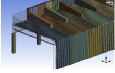
The geometries for these analyses are relatively straightforward and are created within either Autodesk® Inventor®, ANSYS Design Modeller TM or SpaceClaim® and a geometric model can be seen below left with the subsequent Finite Element (FE) model in the graphics below right. The models are meshed entirely with solid elements. The geometry and meshing can be controlled with design parameters allowing for the analysis of differing design options relatively quickly and easily. Iterating on the design parameters also enables design optimization to be performed which can, for example, conduct optimum material selection, thickness or geometric positioning.
The material properties, loading conditions and constraints are applied with extensive use being made of the DGA material database. Because of the unique capabilities of DGA in being able to conduct physical blast and impact testing the non-linear failure of these complex materials are validated for use in the analysis calculations that we perform. The loading is applied in the form of a pressure time history and is applied to the face of the glass panel.
The results obtained from these analyses directly allow for the evaluation of the design versus the above failure criteria, establishing whether the glass panel is likely to leave the balustrade base support, whether delamination in the glass panel will occur, and to what level. It is also possible to erode the materials with a failure criterion in order that the number and mass of fragments can be evaluated according to the design criteria. An example of the material erosion is shown in the graphic to the right indicating material failure in the interlayer. The time history of the reaction forces, in all directions, can also be evaluated allowing for the subsequent design of the base support fixings into ground. An example is shown in the graphic to the left illustrating the reaction loads in the base support in the direction of the blast pressure wave. Another example of the use of the eroded material failure analysis is illustrated in the graphic below left which shows the small amounts of failure that can be anticipated in the silicone based bonding compounds used to fix the glass panel into the base support. It can be seen that small amounts of material can be expected to tear, however, the main function of the bond remains intact The graphic to the right illustrates a balustrade design that is subjected to a significant blast event and 1s designed to satisfy the blast design criteria, in that the panel remains intact, however, the panel will “flop” over on its supporting structure but remain connected to it. A small amount of cuboid delaminated glass will be projected but the analysis will also predict the size, total mass and subsequent trajectory of these fragments.


Benefit
The analysis capabilities described here have helped many of DGA’s clients ensure that their balustrade designs are suitable in terms of the specific threat posed in the specific location and ultimately protecting the public from the fragments and debris which have been shown to be the major cause of life changing injuries sustained as a result of these unfortunate events. This benefit can be accrued prior to the manufacture of any of the actual components and usually conducted many months in advance of the installation of these systems. An extreme example of virtual prototyping in action.