Blast Analysis of Petrochemical Facilities
Background
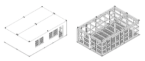
For quite a number of years, assessments have been required to be made on the blast resistance of any occupied buildings, such as Control Rooms, in petrochemical facilities. An example of these efforts can be seen in the American Society of Civil Engineers (ASCE) document: Design of Blast-Resistant Buildings in Petrochemical Facilities. This document provides an excellent basis for the establishment of loading conditions, evaluation of construction methods and provides recommendations on design and design acceptance. The need to protect personnel from the hazards of accidental explosive blast being the clear objective in these assessments. There are two common forms of construction for control rooms that we have evaluated, i.e. Reinforced Concrete permanent structures or steel ISO Container semipermanent facilities, see image to the left. These facilities are specifically designed to withstand blast and to dissipate blast energy through allowable plastic deformation, or cracking, in order to protect occupants against damage and injury from an explosion. The design of the facility is specific to the building location and threat. Moreover, because blasts of different pressure amplitudes and duration (impulses) are expected, the design of the facility would also be robust to any of these variations. A facility would be ‘rated’ to a certain pressure, designed by the manufacturer to resist a certain dynamic impulse with some permanent deformation. The ASCE document above provides criteria for assessing this permanent deformation. Construction materials, primary or secondary members in the design as well as definitions of acceptable Low, Medium or High Response categories are used to specify limits for Ductility Ratios and Joint Rotations.
Analysis
DGA have been commissioned to demonstrate, via finite element analysis (FEA), that the design criteria may be met for a reinforced concrete or ISO container type of facility design subjected to a blast load. FEA provides a more comprehensive prediction of non-linear dynamic effects than other techniques such as single degree of freedom methods. ANSYS Explicit is used for this purpose.
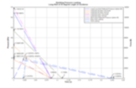
The ANSYS Explicit program is based on the solver of the ANSYS AUTODYN analysis program and is fully integrated into the ANSYS Workbench environment. The Explicit program requires a pressure time history load (shown in the image to the right) to be defined from the ASCE document for all risk scenarios (blast direction and building orientation). The geometries for these analyses are relatively straightforward and are created within either Autodesk Inventor, ANSYS DesignModeller or SpaceClaim and a geometric model for an ISO Container type can be seen to the left with the subsequent Finite Element (FE) model in the graphics to the right.
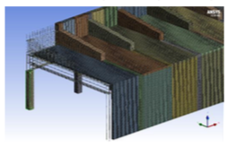
For the RC type of facility design the embedded steel reinforcement mesh can be seen in the geometry image below left resulting in connected, and embedded, beams being included within the mesh. The concrete is meshed entirely with solid elements and the steel with beam elements. The geometry and meshing can be controlled with design parameters allowing for the analysis of differing design options relatively quickly and easily. Iterating on the design parameters also enables design optimization to be performed which can, for example, conduct optimum material selection, thickness, rebar diameter or geometric positioning.
The material properties, loading conditions and constraints are applied with extensive use being made of the DGA material database. Because of the unique capabilities of DGA in being able to conduct physical blast and impact testing the non-linear failure of these complex materials are validated for use in the analysis calculations that we perform. The loading is applied in the form of a pressure time history and is applied to the face of the panel.
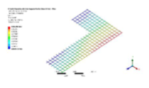
The results obtained from these analyses directly allow for the evaluation of the design versus the previously mentioned failure criteria, establishing whether the facility is fit for purpose, or not. The time history of the reaction forces, in all directions, can also be evaluated allowing for the subsequent design of the structural connections (welds, bolts, rivets, etc.) and base support fixings. An example is shown in the graphic below right illustrating the reaction loads in the base support in the direction of the blast pressure wave. The graphic above right illustrates a temporary ISO Container design which isn’t fixed to ground and the level of frictional sliding can be predicted.
Non-linear material behaviour for steel and concrete, including damage and failure criteria, can be included in the analyses facilitating the prediction of joint rotations and ductility ratios accurately.
The graphic below right illustrates the assessment that can be performed on the steel reinforcement The steel reinforcement ensures that the bulk of the concrete remains in place. Should failure occur in the steel then there is the potential for large, heavy, fragments of concrete and steel to be projected and to cause considerable injuries. A small amount of concrete will be projected but the analysis will also predict the size, total mass and subsequent trajectory of these fragments. Thus breaching, spalling and scabbing can be assessed.


Benefit
The analysis capabilities described here have helped many of DGA’s clients ensure that their inhabited petrochemical facilities are suitable in terms of the specific threat posed, in the specific location, and ultimately protecting personnel from blast as well as the fragments and debris which have been shown to be the major cause of life changing injuries sustained as a result of these unfortunate accidental events. This benefit can be accrued prior to the manufacture of any of the actual components and usually conducted many months in advance of the installation of these systems. An efficient example of virtual prototyping within structural engineering.


